Search This Blog

Monday 12 September 2022

OSPF Operation and Route Selection - A detailed discussion

 OSPF Routing Protocol


Abstract:

              The report discusses the OSPF Routing protocol and its implementation in networks. There are different routing protocols supported by modern communication devices but how OSPF stands out as a unique protocol will be discussed in the report. OSPF   is a dynamic routing protocol developed by IETF International Engineering Task Force in 1989. OSPF uses a link-state algorithm known as the Dijkstra algorithm. The algorithm uses a mechanism to find the shortest path between the source and the destination. In link state routing the network topology and cost of all links are known. These link state packets are broadcasted to all the connected nodes in the network. OSPF divides the networks into different administrative domains called Areas. The reason behind this logical network division is to reduce the broadcasting in the whole network by limiting it to a specific group. OSPF grouping reasonably reduces the troubleshooting problems by confining each update or issue to the same area. In a bigger OSPF network, there can be multiple Areas these areas must be centrally connected to the Backbone or Area 0 network. This is Area 0 that helps in exchanging information between the other Areas and the concept is called Multi Area OSPF.

Introduction:

Routing is a layer-III concept in which information on routes is exchanged between different networks. The route information exchange between different networks is achieved by either adding the required manually or we use any protocol to do that. The concept of manual addition of routes to a router is called static routing and the routing exchange achieved by using a protocol is called dynamic routing.

OSPF is an interior gateway dynamic routing protocol that is used to exchange routing information between different networks but within the same Autonomous System. OSPF is one of the IP routing protocols that work on port number 89. For the initial database setup, it uses broadcasting on the IP address 224.0.0.5. The link state algorithm of OSPF collects link state information from all the connected networks which is called the link state database. OSPF advertises the directly connected networks for routing information exchange, after successful advertisement OSPF neighborships are established between the devices through which routing information’s exchanged.

OSPF is best suited for large complex networks that contain many sub-networks. These sub-networks are divided into Areas and all areas must be connected to Area0 for successful communication. Unlike RIP and other routing protocols, OSPF only shares the change that occurred in a network it doesn’t share any information with its neighbors when everything is running smoothly.

OSPF Operations

OSPF is a link-state routing protocol that is the most loved and famous enterprise network protocol. It is one of the best available Interior gateway protocols due to its unique features.

When OSPF is configured in a network for the first time, OSPF-enabled routers start listening to the neighbor OSPF-enabled routers for the collection of links state information. This link state information is gathered through the interfaces that connect one router to another OSPF router. At the end of the listening phase, the OSPF router saves the information to a database called link state database or LSDB. After gathering link state database information,

the OSPF router runs the Dijkstra algorithm or shortest path first (SPF) to convert the link state database to three different tables. One of the tables will be the one used for the shortest path calculation from the router to the destination network.

The OSPF operations can better be demonstrated using the below network diagram. Here we are having two networks connected to R1 and R5 and traffic has been generated from PC-A to PC-B. But before that OSPF routing protocol has been configured on the routers. All the routers in the below network belong to Area 0. Soon after the OSPF configuration, every router will try to find the neighboring router through the interface connecting to the neighboring router.

During this process, the OSPF routers will form neighboring adjacencies by going through different stages. Every router will form a neighbor adjacency with the other connected OSPF routers. After adjacencies, the router try to find the best path to PC-B from PC-A. OSPF cost of all the paths that connect it with Network PC- B. Based on this path cost OSPF router selects the best path towards the target network. The path having the lowest cost is considered the best path.

In the above scenario, the PC-A has 15+ paths and OSPF will select the best path by calculating the cost of each interface.

Based on the interface cost of interfaces, the router R1 will select the highlighted path of the PC-A traffic because the highlighted interface has the lowest cost. This is the best network route and the OSPF router will keep this routing information in the routing table. The routing will not change until and unless any change occurs in the network.

If any link between R1 and R5 doesn’t break path will remain the same but when a link failure occurs, OSPF will again run the Dijkstra algorithm to find the next best available path in the above diagram the values shown with each link is the link cost. The link cost is calculated with the formula below.

            cost = reference bandwidth / interface bandwidth

Here cost of the interface is calculated by dividing the reference bandwidth by the bandwidth of an OSPF-enabled interface. Below is the reference chart for OSPF costs.

Interface

Bandwidth

OSPF Cost

Gigabit Ethernet

1 Gbps

1

Fast Ethernet

100 Mbps

1

Ethernet

10 Mbps

10

E1

2 Mbps

48

T1

1.55 Mbps

64


Advantages of Configuring OSPF In a Network

·        There are no hop limitations in OSPF like we have in some other protocols like RIP and IGRP.

·        OSPF has a very fast convergence and calculates the next path in instants when the PR path goes down.

·        It divides the administrative networks into different areas for easy management and Maintenance.

·        Provides the effective use of VLSM.

·        Supports load balancing, Active and backup configurations.

OSPF Implementation and Configuration

OSPF protocol is used for large networks where network reliability, network Scalability, network redundancy is, and load balancing is valued. The implementation of OSPF in an enterprise network provides us with the above advantages.

When the OSPF is configured for networks that have a single group we call it single Area OSPF and when the network is a combination of many groups such a network is called Multi Area OSPF. In the below network we will configure a multi-area network OSPF network and analyze the routing tables.

 The above network of multiple paths when a packet travels from PC1 to PC2. The packet has three paths when it reaches R1. The paths have different costs due to different types of cables. The top path is having a longer path due to the number of routers in between but it is using fast ether cable which has a lower cost. The second path is a serial cable-based path which is the shortest path in the network. The last path is also a serial cable-based path. The routing table is then installed according to the shortest and best path. Each router has a database received from the connected router for the formation of routing table.

Each OSPF router is identified with a router ID which is an IP address and is the highest IP address of this router and being used for identification in the network.

For successful routing information, OSPF enabled router to establish neighborship adjacencies which can be queried as below. The neighbor ids are the routers with which this router has established neighborship relations.

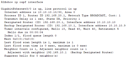
All routers keep checking the neighborship adjacencies by sending hello and keep alive packets. They are set to a specific value and every OSPF router should follow these values for establishing adjacencies. If the hello, dead timer between two routers is not the same, the routers can’t exchange routing information between them. We can confirm the hello and dead time by querying the information of OSPF enabled router interface.


Now Let’s check which path the packet are choosing here when they arrive from the PC-A. The router routing table can be queried to check the status of router of the network 2.

We are receiving the required network 2 routers on R1 through the gigabit Ethernet0/0 which is connected to the top router which is the best path. If this path gets down the router R1 will select the next best path.

Authentication in OSPF

One of the best features that OSPF offers is the authentication that is done to secure the routing updates between OSPF routers. OSPF supports two types of authentication plain text authentication and encrypted MD5 authentication. For the proper function of authentication methodology, all routers should be enabled with the same authentication mechanism.

The Concept of OSPF Virtual Links

One of the mechanisms of OSPF usage is in the formation of Areas and connection of all Areas with the backbone Area or Area 0. But in the case were there is not possible to connect other areas with the backbone areas. In such cases, still, the other Areas are connected to area 0 through some workaround to build a logical connection with area 0.  This mechanism of virtual connectivity is via OSPF virtual links.

OSPF Table Types

OSPF maintains three types which are below.

·        Neighbour Table: Information of OSPF neighbors.

·        Topology Table: Information about the whole topology

·        Routing Table: List of the best route to different networks.


Conclusion

This report discusses the OSPF routing protocol, its implementation in a network, and the configuration steps with advantages. It also discusses the OSPF operations and convergence with the failure testing. We have developed a scenario where we have multiple paths from source to destination and the selection of the best path. We also tested when the best path gets unavailable and how OSPF selects the second-best path. The OSPF cost factor is one of the important factors that can be used for manipulation of the best path and checking the type of interfaces that have different costs and the formula used for cost calculation. On its advantages and other good features, it stands out as one of the best protocols and most used protocols for enterprise networks.


Saturday 10 September 2022

The Future of 5G Technology

5G is the fifth generation in the evolution of mobile communication systems which is an extension of 4G technology. In cellular technologies, usually, the service areas are divided into smaller regions called “cells” and 5G adopts smaller cell sizes as compared to those other cellular technologies. The basic architecture of 5G follows the same architecture as followed by other technologies with some new adaptations on the core side. Whereas the radio access network site still follows the legacy architecture i.e (Base station & Mobile device) The question is why 5G as we have already other cellular technologies?

What is 5G?

5G is the latest development in mobile broadband communication intended for a few features which are either not available in current technologies or do not fulfill the current and future needs.

Below are the main landscapes of 5G for which it is being deployed and developing very swiftly.

·         Provisioning of Higher Data Rates up to 1 Gbps

·         Reducing Latency to less than 5 Ms.

·         Massive devices support up to 1.2 billion till 2025.

·         Increase System Capacity.

·         Cost effectivity and hardware reduction.

The features of 5G can be summarized as below.


5G Architecture

The three main differences that 5G is trying to create as compared to LTE are not achievable without modifying the advanced architecture at the Radio and core end. Below is the basic architecture always adopted by mobile communications and equally applicable for all mobile technologies but the one that has made changes to it is 5G.  5G has introduced a few other concepts to improve the latency and other features which we will see later. But the basic concept of transmitting RF waves from the antenna and placing the base station behind it and then the main connectivity with the core is still there.

                                                                (Cellular Communication Basic Architecture)

5G is the technology that has introduced Mobile edge computing that provides service very close to users instead of a Data Center located far apart from the user. This concept has greatly reduced the end-to-end latency and high bandwidth.  Distribution of tasks in such a way reduces the load on a centralized system that greatly improves the performance of each edge data center and centralized main data centers.

The below picture clearly shows the benefits of introducing MEC. If the RAN were connected to the core without deploying edge nodes near to the base station, the distance could be 230 KM which for sure increases the latency and has an impact on throughput, but the deployment of edge cloud has minimized the distance.


                                                            (5G Architecture)

The Future of 5G

After the introduction of IoT and IOE, the need for 5G has grown massively because it is the only technology that can help us to develop SMART solutions. The applications related to health care and vehicle-to-vehicle communication are still waiting for ultra-low latency for instantaneous communication for automated and unmanned vehicles. Augmented reality and virtual reality need bandwidth in Gbps for proper function and 5G is the most suitable technology to support this. The industrial application of robotic technology needs 5G keenly to unburden man in unreachable places and difficult to work environmental conditions.

In short 5G is going to be the technology of the future that will unveil the 4th Industrial Revolution. In Some parts of the world, 5G has been deployed as NSA technology and very good results have been achieved. 5G is going to bring a revolution in terms of the economy as the sale of 5G supporting mobile devices already has increased and increasing day by day.

5G is expected to increase the economic output to $3.6 trillion in the international market by 2035 and it will be one of the best markets to introduce 22.3 million jobs. The markets that will grow due to 5G in the future are listed below.

·         AR/VR Market

·         Autonomous Cars

·         Drone Planes and Cameras.        

·         Film industry

·         Robotic Technologies.

·         Artificial Intelligence.

·         Cloud Computing

·         Online Gaming

·         Mobile Manufacturing Companies

·         Educational institutes.

·         Machinery and Equipment.

·         Energy

·         Health Care.

These are the stakeholders that will take the highest benefit from 5G technology and life after 2035 would be much different from today. Most of our routine work will be performed by machines and machines would communicate with each other without human intervention. That would be an era where our fridge will order cold drinks itself, home automation will be fixing faults through its own processes. Cars will be moving automatically, and accidents will be reduced.

Considering the current landscape of 5G and its penetration in the future market, it is the most anticipated technology, that will bring revolution in human life’s.


Mobile Networks - Authentication Security in 4G & 5G

 ·         Introduction

Mobile Networks are telecommunication networks where we do not have any physical link between the end-user devices and the base transceiver station. The medium between these two is a wireless link through which the end-user gets connected to a mobile network. The device that radiates frequencies is called RF Antenna which can receive the traffic from the end devices.

In the case of mobile networks, the section from a mobile device to the base receiver station is always wireless and the network here onwards is a connected physical network. A sample mobile network architecture has been shown below.

The major concern in mobile networks is the security of the end-user data and the proper recognition of authorized devices to access the network. Therefore, certain authentication procedures are used to authenticate the desired devices.

We will discuss the importance of authentication and procedures in LTE and 5G in the following paragraphs.


·         Why do we need authentication in mobile networks?

Mobile networks have made our lives very easy in terms of communication, video, voice, and data sharing. We are connected to each other via our mobile sets and sharing live activities and may be enjoying a cricket match from our favorite location. The time to get tied to Television sets is history now.

But with these facilities, we have encountered privacy and security issues related to privacy and data security. Therefore, the providers are using security technologies to protect our data and privacy.

Authentication is one of the most important aspects that every mobile network must support whether that is a 3G, 4G or, 5G network. Every company prefers the authentication of its users to enable security. In the case of mobile networks, we have a central database where we create a profile for every user in our network. When the user tries to access the network, the device information is forwarded to a dedicated server which matches the profile information with the incoming connection request. When the received information is accurate the node allows the user to access network resources.

So, the core purpose of authentication is to ensure security by either forwarding the user request to access the network or rejecting the unauthorized request for network access. Through the authentication procedure, mobile networks make sure that the traffic transferred over the wireless links is secure and not manipulated by a man in the middle between the device and the base station.

·         Authentication in 4G Networks.

The term LTE is used for “Long term Evolution” which is a form of wireless broadband communication. This technology was designed to provide high-speed data internet only, voice calls are not supported by LTE rather VOIP or VoLTE is used for voice calls over internet protocol. LTE uses a group of transmitting and receiving antennas at both the mobile site and at the base station side. The base station is known as eNodeB in LTE which supports multiple parallel streams to send and receive data.

Below is the LTE architecture and the node that is related to authentication is the home subscriber server (HSS) which is connected to the mobility management entity for receiving and sending subscriber information.


If we study the call flow of LTE, it starts from the UE, which sends attach request towards the enodeB, which directs the attach request towards the MME. Then MME verifies the authenticity of the connection request.  

Below are the authentication procedures that LTE uses for ensuring the security and authentication of incoming connection requests.

LTE Networks are using two security procedures for customer and network information security at two different levels.

·         RRC and User Plane Security between the UE and EUTRAN.

The RRC security association ensures security between the UE and EUTRAN before the subscriber accesses the core network and reaches HSS.

·         NAS Security association between UE and MME.

NAS is the non-access stratum that ensures the security of data transmission between the UE and MME it uses ciphering and protects the integrity of subscriber’s data.

After the association of the device with the core network below are the security procedures parameter that is used for authentication of the subscriber request.

·         RAND: Random Challenge

It is a random value generated by MME and provided to the UE to decode and UE runs an algorithm. The length of the random number is 16 octets.

·         AUTN: Authentication Token

An authentication token is used to provide the authentication information to UE. This is a way to authenticate the network by the UE to check if the network is the one it wanted to get connected.

·         XRES: Expected response

XRES is a parameter that is generated by the MME and sent to HSS and UE, it monitors if both can generate the response that MME expects.

·         EPS-AKA (Evolved Packet System Authentication and Key Management)

This procedure triggers when the UE gets through the initial attach procedure at the EUTRAN end. When it reached the core network MME sends an authentication request message to the HSS. This authentication message consists of UE-related identities like IMSI, PLMN ID, GUTI, etc. The information also contains some authentication vector information which is decoded by HSS and send back to MME and this message is called the Authentication response message.

MME then sends an authentication request to the UE with some authentication vectors and expects a response that MME already generated. When the same response is generated by UE also, this procedure gets completed and both device


·         Authentication in 5G

5G is the latest wireless broadband technology that targets three main things that can’t be provided by current technologies.

ü  eMMB: Enhanced Mobile broadband

ü  URLLC, Ultra reliable low latency less than 1ms.

ü  mMTC, Massive machine type communication.

5G is the ideal technology that supports IOT and smart cities and large industrial requirements.


UDM or unified data management is the main node associated with the authentication and database of the 5G networks. 

5G is a service-based architecture and uses three main security procedures.

·         5G AKA: Authentication and Key Management

·         EAP-AKA: Extensible Authentication Protocol-AKA

·         EAP-TLS: Extensible Authentication Protocol-Transport layer security.

In 5G both AUSF and UDM support authentication functions where the first two procedures are the mandatory authentication procedures and the third one is an optional function. 5G authentication is completed in two phases.

ü  Phase-1: Selection and Initiation of authentication method.

ü  Phase-2: The authentication procedure starts between UE and Network.

After the Selection of the authentication procedure, a few authentication vectors are exchanged and validated at AUSF and UDM. Below is the block diagram showing authentication. 


Below are the necessary authentication vectors used in 5G networks.

EAP-AKA:

It is an authentication procedure in 5G where a cryptographic key is a share between the network and the UE. In the procedure, both network and the UE authenticates each other to ensure the security of information transfer between the network and device.

Here the unified data manager (UDM) generates an authentication vector (AV). Separation for the application management function aka AMF generates a separation bit 1, IK & CK. Then these AV are sent to the AUSF with the instructions to use these authentication vectors for EAP-AKA. The UDF alters these AV (RAND, AUTN, XRES, CK, IK) before it sends them to AUSF.

Conclusion

4G

5G

In 4G authentication HSS & MME plays main role

Entities in 5G are different from 4G particularly SIDF which does not exist in 4G

UE identity over the radio access network is sent unencrypted

The UE permanent ID is always encrypted in 5G

4G authentication is less secure than 5g

5G offers better security with more separation keys


Abbreviation

RF                                                          Radio Frequency

LTE                                                              Long term Evolution

VOIP                                                      Voice over IP

VoLTE                                                    Voice over LTE

HSS                                                             Home subscriber Server

UE                                                          User equipment

ENodeB                                                 4G base station

MME                                                      Mobility Management Entity

SGW                                                       serving Gateway.

PCRF                                                       Packet and Charging rule function.

Pgw                                                         Packet Gateway

SAE                                                          Service Architecture Evolution

RRC                                                         Radio resource Control

EUTRAN                                                 Evolved Universal terrestrial Radia access network.

NAS                                                         Network access stratum

IMSI                                                        International mobile subscriber’s identity

gNB                                                         5G Base station

AMF                                                        Application management function

SEAF                                                        Security Anchor Function

AUSF                                                       Authentication server function

UDM                                                       Unified data management

GUTI                                                       Globally unique temporary identity.

CK                                                           Cipher key

IK                                                            integrity Key


Thursday 8 September 2022

OSPF Routing Protocol Configuration (Single Area and Multi-Area OSPF)

 Unlike other routing protocols, OSPF does not carry data via a transport protocol (UDP, TCP). Instead, OSPF forms IP datagrams directly, packaging them using protocol number 89 for the IP Protocol field.  It is an IGP means an interior gateway routing protocol that is used for communication in the same autonomous system. OSPF is the most loved protocol in the industry due to its useful features. From the calculation of the routes in the network, it uses an algorithm called Dijkstra Algorithm which calculates the shortest path from source to destination. Initially, all OSPF routers gather the information of their connected networks which is called link state database LSDB, then they share this information with other OSPF routers, and then the information is populated in the whole network. After gathering information the routers start calculating their shortest path to the destination, this calculation is based on the total cost through an interface.

Based on the configuration type, OSPF can be used in a single-area network or a multi-area network.

·         Single Area OSPF

Here we have only one area for all routers and that is Area 0 which is also called the backbone area. We use single area OSPF for comparatively small networks.

·         Multi Area OSPF

Large networks are divided into different areas to reduce the number of link state advertisements and other OSPF overhead traffic. This traffic is confined to the same area and not shared with other areas.


This division of a network into areas give us a concept of different type of routers based on their location in the network. Below are the different router types of an OSPF network.

Router types

·         Internal router (IR): Router located in a specific area.

·         Area border router (ABR): This router has one leg in Area 0 and another leg in any other Area.

·         Backbone router (BR): Router Area 0 is called backbone router,

·         Autonomous system boundary router (ASBR): The boundary router after which a different autonomous system with a different routing protocol starts

Router id

The unique ID for the Router in the OSPF topology is known as the Router ID. The router ID is a 32-bit IP address assigned to each OSPF router.OSPF router ID should not be changed once the neighborship establishes because changing the router ID resets the OSPF Process and neighboring routes get reset.

·         Router ID can be configured manually.

·         If no router-id is configured, the router makes the highest loopback IP as the router ID.

·         If no loopback IP is configured, a router selects the highest active interface as the router ID.

We can configure router ID using the below commands

R1>enable

R1#configure terminal

R1(config)#router ospf 100

R1(config-router)#router-id 10.10.10.10

R1(config-router)#exit

R1(config)#exit


Router Attributes

·         Designated router (DR): A router that is the main centralized router that controls an area.

·         Backup designated router (BDR): It acts as an assistant of the DR routers and acts as DR in case of failure of the DR router.

OSPF neighborship establishes after exchanging certain messages that are called Link state advertisements. Below is the message type that OSPF routers exchange with each other.

OSPF messages

·         Hello -> used by a router to discover neighbor routers and establish neighbor adjacency

·         Database Description (DBD)

·         Link State Request (LSR)

·         Link State Update (LSU)

·         Link State Acknowledgment (LSAck)


Single Area OSPF Configuration 

In single area OSPF, we have the same Area for all networks and the area is normally Area 0. Here we are again using the same topology now configured with the OSPF routing protocol.

Below are the configuration steps for the OSPF routing protocol.

R1

The connected routes of R1 are advertised in OSPF process 1 and Area 0.

R1#conf t

R1(config)#router ospf 1

R1(config-router)# network 10.10.10.8 0.0.0.3 area 0

R1(config-router)# network 192.168.10.0 0.0.0.255 area 0

R1(config-router)#exit

R2:

For successful neighborship between the two routers the Process ID, Area number, and the point-to-point network should be correctly configured.

R2#conf t

R2(config)#router ospf 1

R2(config-router)# network 10.10.10.8 0.0.0.3 area 0

R2(config-router)# network 192.168.20.0 0.0.0.255 area 0

R2(config-router)#!


After the configuration of the above steps on both of the routers, a successful neighborship is established between the routers, and this neighborship can be checked with the below command.


As the neighborship has been established, now the routers can successfully share their network information with each other in the form of the routing table.

Router R1 is learning the network connected to R2 through OSPF protocol and R2 should learn the networks connected to R2.

The information of router ID, subnets, Area, and all OSPF advertised networks can be seen with the below command.


The status cost and states of OSPF at the interface level can be queried with the below command.


Multi-Area OSPF Configuration 

In multi-area OSPF as the name indicates, we have multiple areas at least two. The main requirement of Multi Area OSPF is that all other areas should be connected to Area 0 to exchange routing information.

Let’s take the below topology where we have two different areas (Area 0 and Area1 ) communicating with each other. The routers that are having one leg in the other area are called ABR or Area border routers. In our topology, ABR_0 and Rarea1_1 are the area border routers.


Let’s see the configuration of the Area border routers which enable the communication between the routers.

RArea1_1

RArea1_1#conf t

RArea1_1(config)#router ospf 1

RArea1_1(config-router)# network 11.11.11.4 0.0.0.3 area 0

RArea1_1(config-router)# network 11.11.11.8 0.0.0.3 area 1

RArea1_1(config-router)#!


On the router RArea1_1, we have configured the above networks according to the location of their networks. One leg is connected to Area0 and the other is located in Area1.

ABR_0

The below configuration has been done of the Area 0 ABR routers to establish neighborship relation with the other ABR of Area 1

ABR_0#conf t

ABR_0(config)#

ABR_0(config)#router ospf 1

ABR_0(config-router)# network 10.10.10.8 0.0.0.3 area 0

ABR_0(config-router)# network 192.168.20.0 0.0.0.255 area 0

ABR_0(config-router)# network 11.11.11.4 0.0.0.3 area 0

Each ABR has established two neighborship relations, one with its local router and the other with the other Area, Area Border router.

Routing Table of Multi-Area OSPF

ABR_0

The routes with “O IA” are the inter-area routes, this router is getting these routes from a different area and that is Area 1.


RArea1_2

The router RArea1_2 is learning below “O IA” routes from Area 0 via its area border router


Packet Tracer file with configuration logs and script is available and may be provided upon request 


OSPF Operation and Route Selection - A detailed discussion

  OSPF Routing Protocol   Abstract:               The report discusses the OSPF Routing protocol and its implementation in networks. T...