Below is the network diagram we are having for designing a network, where two different networks are connected to two routers. One of the networks is connected directly while the other network is connected to a router through a Switch.

1. Addressing Scheme
For the proper communication between the
devices, we need IP planning. The IP plan is generated using the provided
network address. In this network, we will be using 192.168.10.0/24
for subnetting. The IP subnetting, we are using, in this case, it s a fixed-length subnet mask and needs to break down the network into 8 sub-networks.
Subnetting is done by borrowing bits from the host part and keeps
borrowing till we satisfy the need of the network. In the above scene,ario we
need a total of 8 subnets so below is detailed subnetting steps. Above
is the network diagram where Host 2 is connected to Renewing router and Host1
is connected to a switch which is further connected to the Veterinary router.
Basically, the networks connected to the routers on their giga Ethernet ports
are local Area networks and the two routers have a WAN connection between them.
The WAN connection is a serial connection. Above is the network diagram where
Host 2 is connected to Renewing router and Host1 is connected to a switch which
is further connected to the Veterinary router. Basically, the networks
connected to the routers on their giga Ethernet ports are local Area networks
and the two routers have a WAN connection between them. The WAN connection is a
serial connection
192.168.10.0/24
Subnetworks Calculation formula = 2n
(n= bits borrowed)
Here the number of subnets required is =
8
So,
8=2n =>=>=> 23=2n and now n=3, So
to get 8 subnets from the above Class C IP address we need to borrow three bits
from the host part. In class C the last octet with 8 bits is dedicated to hosting.
So
192.168.10.0/24+3 = 192.168.10.0/27 is the
new cider of the above network and
Host per subnet is calculated as =2n-2
(n= remaining host bits)
=25-2=
30 hosts per subnet
The above subnets can be written as
below. That are total of 8 bits from subnet Zero through Subnet seven.
|
No |
Subnet |
First host |
Last host |
Broadcast |
Subnet mask |
|
0 |
192.168.10.0/27 |
192.168.10.1 |
192.168.10.30 |
192.168.10.31 |
255.255.255.224 |
|
1 |
192.168.10.32/27 |
192.168.10.33 |
192.168.10.62 |
192.168.10.63 |
255.255.255.224 |
|
2 |
192.168.10.64/27 |
192.168.10.65 |
192.168.10.94 |
192.168.10.95 |
255.255.255.224 |
|
3 |
192.168.10.96/27 |
192.168.10.97 |
192.168.10.126 |
192.168.10.127 |
255.255.255.224 |
|
4 |
192.168.10.128/27 |
192.168.10.129 |
192.168.10.158 |
192.168.10.159 |
255.255.255.224 |
|
5 |
192.168.10.160/27 |
192.168.10.161 |
192.168.10.190 |
192.168.10.191 |
255.255.255.224 |
|
6 |
192.168.10.192/27 |
192.168.10.193 |
192.168.10.222 |
192.168.10.223 |
255.255.255.224 |
|
7 |
192.168.10.224/27 |
192.168.10.225 |
192.168.10.254 |
192.168.10.255 |
255.255.255.224 |
According to instructions subnet,
Zero and subnet seven cannot be used for our network. Therefore, we are using subnets
1, 2 & 3 for our network.
1.2 Device IP addresses:
The below IP addresses have
been assigned to the interfaces of the routers and hosts. The first IP address in
each subnet has been assigned to the router interface IP and the second IP to
the PC.
The gateway IP assigned to
every PC is the interface ip of the router connected to the PC
|
Device |
Port |
IP address |
Subnet mask |
Default Gateway |
|
Vetinari |
Ethernet 0/0 |
192.168.10.33 |
255.255.255.224 |
N/A |
|
Vetinari |
Serial 0/2/0 |
192.168.10.65 |
255.255.255.224 |
N/A |
|
Rincewind |
Ethernet 0/0 |
192.168.10.97 |
255.255.255.224 |
N/A |
|
Rincewind |
Serial 0/2/0 |
192.168.10.66 |
255.255.255.224 |
N/A |
|
Host 1 |
Ethernet |
192.168.10.34 |
255.255.255.224 |
192.168.10.33 |
|
Host 2 |
Ethernet |
192.168.10.98 |
255.255.255.224 |
192.168.10.97 |
2. Cabling
Cabling is the selection of
appropriate cables for connecting the networking devices with each other. In
our network designed below, we have connected the host pcs with the router and
switch. The cable from the PC to the Switch in the Vetinari network is a straight-through
cable and from the switch to the router, it’s again a straight-through copper
cable. The cable between host pc 2 to the router is a cross-over cable and the
cable between the two routers is a serial cable. The serial cable used in this network shows that
there is a good distance between the two routers.

Initially, when the network is deployed, we used a console cable to get connected to a switch or router to do configurations. The cable shown in the above snapshot is the console cable being used for the configuration of networking devices.
·
The
serial cable that is connected to Vetinari is a Data terminating end and the other
end is connected to Rincewind which is the DCE or data communication end that
provides a clock to the network.
3. Basic router commands & Modes
The configuration of a router is done through a command from the command line interface or CLI. To run these commands, we need different privilege levels. The privilege level of a router is set in different modes of a router.
User-Exec mode
The mode which we access
after just logging into a router is called “User Exec Mode” and very few commands
can be run over here.

To check the type of commands
we run in user exec mode, we type question marks which show us the commands we
are allowed to use. Below is the list of some commands with their function that
can be run in privilege mode.
|
|
Command |
Function |
|
1 |
enable |
Turn on privileged commands |
|
2 |
exit |
Exit from the EXEC mode |
|
3 |
terminal |
Set terminal line parameters |
|
4 |
ping |
Send echo messages |
|
5 |
logout |
Exit from the EXEC |
|
6 |
ssh |
Open a secure shell client connection |
|
7 |
show |
Show running system information |
|
8 |
traceroute |
Trace route to destination |
Privilege mode
Below is the list of commands that
can be run in user privilege mode. The number of commands that can be run in
this mode needs more privileges and below are a few commands.
To enter this mode, we need to type the “enable” command and the view of the router becomes like below.

We have selected below privileged exec mode commands prompting when
question mark is typed in this mode.
|
|
Command |
Function |
|
1 |
ping |
Send echo messages |
|
2 |
copy |
Copy from one file to another |
|
3 |
setup |
Run the SETUP command facility |
|
4 |
erase |
Erase a filesystem |
|
5 |
debug |
Debugging functions |
|
6 |
traceroute |
Trace route to destination |
|
7 |
configure |
Enter configuration mode |
|
8 |
clear |
clear Reset functions |
4. Basic router
configuration
Global configuration mode
This is the mode that needs the highest level of privilege, we must move
into this mode to modify, add, or remove the configuration of a network. All
configurations we have done in this network need to move into privilege mode.
Below is the list of commands that we can run in this mode. We enter configuration
mode by typing “config terminal” in the user privilege mode.

We
have run the below commands on these routers for the configuration of this
network.
We
start from the configuration of the device name to the whole configuration.
4.1
Router names: hostname is the command to change the router name to a new
name
Router(config)#hostname
Vetinari
Router(config)#hostname
Rincewind
4.2 Interfaces: The mode we use to
assign interface IPs and interface activation is done in this mode also called interface configuration mode.
Below are the steps to set the interface IPs of a router.
// Ethernet port for
Vetinari:
Vetinari(config)#interface
FastEthernet0/0
Vetinari(config-if)# ip address
192.168.10.33 255.255.255.224
Vetinari(conf-if)# no shutdown
// Ethernet port for
Rincewind:
Rincewind(config)#interface
FastEthernet0/0
Rincewind(config-if)# ip address
192.168.10.97 255.255.255.224
Rincewind(config-if)#no shutdown
// Serial port for
Vetinari:
Vetinari(config-if)#interface Serial0/2/0
Vetinari(config-if)# ip address
192.168.10.65 255.255.255.224
Vetinari(config-if)#no shutdown
// Serial port for
Rincewind:
Rincewind(config-if)#interface
Serial0/2/0
Rincewind(config-if)# ip address
192.168.10.66 255.255.255.224
Rincewind(config-if)#clock rate 56000
Rincewind(config-if)#no shutdown
4.3
Setting up passwords
The password of a router or a switch is set to ensure the security of devices.
On a router or a switch, we can set Console password, Line vty password, and
enable password. Below are the configuration steps to do that.
// Passwords for telnet
session (enter line configuration mode)
Vetinari(config)#line
vty 0 4
Vetinari(config-line)#password cisco
Vetinari(config-line)#login
Rincewind(config)#line vty 0 4
Rincewind(config-line)#password cisco
Rincewind(config-line)#login
// Console and
privilege mode passwords
Vetinari(config)#enable password cisco
Vetinari(config)#enable secret class
Rincewind(config)#enable
password cisco
Rincewind(config)#enable secret class
Cisco is the console
and vty password and class is the privilege mode password.
5. Making the
network a working Network
Until and unless all devices are not properly connected and configured there will be no information exchange between the devices. We have configured the computers and all other devices to make them work.
5.1 Configuring the computers:
The computers have been assigned with the above-mentioned IP address to make the work properly and below are the screenshots showing the IP assignment. When correct IP addresses are assigned to the PC and the router-connected interface, we get a ping response from the router-interface IP.
Below
is the ping verification from the host to interface IPs after the correct
configuration
Host 2 to its default
Gateway
Host2 can ping its default gateway IP which
means configuration is fine from the PC to the router.

Host 1 to its Default Gateway

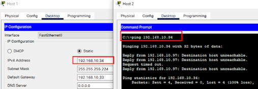
But in this case, all point-to-point links should be able to ping each other like the end IP’s of the serial links should also ping each other like below.
Host 2 cannot ping Host 1
Host 2 can’t ping Host
1 because there is no routing enabled between the two routers.
But
in this case, all point-to-point links should be able to ping each other like
the end IP’s of the serial links should also ping each other like below.

Configuring RIP: Routing Information Protocol
RIP is one of the oldest routing protocols used for enabling routing in smaller networks for up to 15 consecutive hopes. Due to this and some other issues, a few other protocols are preferred in networks now. The configuration of RIP is simple.
The theme of enabling a routing protocol is to advertise the connected
networks, which can be queried as below.

We have used the below steps to enable RIP routing in the network by
advertising the above-connected routes.
Vetinari Router
Vetinari(config)#router rip
Vetinari(config-router)# version 2
Vetinari(config-router)#no auto-summary
Vetinari(config-router)#network 192.168.10.32
Vetinari(config-router)#network 192.168.10.6
Rincewind Router
Rincewind(config)#router rip
Rincewind(config-router)#version 2
Rincewind(config-router)#network 192.168.10.64
Rincewind(config-router)#network 192.168.10.96
Rincewind(config-router)#no auto-summary
6. Testing the network
After
the configuration of the RIP protocol, the routers should be able to exchange
routes with each other and the host should ping each other.

Host1
can ping the hsot2 lying on a different network. Now, these hosts can ping any
IP within the network because all connected routes have been advertised successfully
and we can query the routes of one network on the other router to verify this.

From the above routing table of Rincewind, we see that it receives the routes of host2 through RIP protocol through the serial link se0/2/0.
6.2 Ping host from each router
Ping to both hosts from
Vetinari Router

Ping
verification

Trace
the Route
The successful testing is conducted using the ping and trace route tool,
we use traceroute to check the path from source to destination which is
successful.

6.4 Telnet to Vetinari from Host 2
Telnet is a remote
management protocol, which is used to access devices from a different network
for maintenance. We have configured the routers for remote management using the
telnet protocol. Which is successful.


No comments:
Post a Comment