Introduction:
We have been tasked to design and simulate
network design for the company. The company has seven departments. Each
department has to be segregated by using VLAN. The host requirement of each
department is as below:
|
S.No. |
Department |
Hosts
Required |
|
1 |
Marketing & Sales |
40 |
|
2 |
PR |
15 |
|
3 |
Customer Support |
20 |
|
4 |
Human Resources |
10 |
|
5 |
CEOs & VPs |
10 |
|
6 |
Multimedia Team |
15 |
|
7 |
IT |
5 |
We also need to add severs in the design
that will be used by departments of the company. We are naming this company
“ABC”.
Network Design:
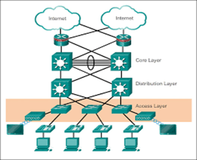
We are designing this network based on
cisco three-tier architecture, the three-layer of this network will be as
below:
1.
Access Layer
2.
Distribution Layer
3.
Core Layer
Below is the
standard cisco proposed design for enterprise networks with great fault
tolerance capabilities.
Access Layer:
This is the first layer of the network from an end-user point of view. The end devices like PCs, laptops, Access points, and
servers are connected to this layer for accessing the core network.
We have certain access layer technologies
to make this layer highly fault-tolerant and make it scalable.
·
VLAN Configuration
·
Switch access and trunking
protocol like VTP
·
Spanning tree protocol
configuration for fast convergence of the network.
·
Port security for limiting
access to the network.
·
Multi-layer authentication
·
Secured remote access for
management
All end devices in this layer will be
connected using CAT-6 cable with layer 2 switching providing speed up to 100
Mbps.
Distribution Layer:
As per cisco's recommended design, the layer
above the access layer is the distribution layer. In this layer normally we used
high performance layer-III switches which has fast switching capacity and more
1Gig ports for further connectivity with the access layer switches.
This is the layer where traffic filtering
policies and VLANs are configured for network security and high scalability. We
use this layer to provide redundancy to layer 2 or the access layer.
This layer will facilitate our end users
with different protocols and to make our network user experience up to the
level. We will be using the below protocols at this layer for our network.
·
DHCP for dynamic IP assignment
·
HSRP (To enable 1+1 LAN
redundancy)
·
Inter-VLAN routing
·
Filtering of traffic through
ACL
·
OSPF routing protocol
This layer will be connected with layer two
switches on fast Ethernet port using CAT-6 cables.
Core Layer:
Core layer is the last layer of our
architecture, it will be connected with layer 3 switches of the distribution layer.
It will provide connectivity with ISP, through the dynamic routing protocol. In the future, it can also help us connect to other sites of the company in case of expansion.
This can be done using secure VPN tunneling in which traffic will be
encrypted. This layer will support in below services.
·
ISP connection
·
Firewall Integration
·
Filtering of data
Network Simulations:
Before implementing any network, it is very
helpful to design and implement on simulation software to test the theoretical
approach. We have simulated our network design on simulation software packet
tracer. We have tested all protocols and segregated departments to check the
accuracy of our design and remove all shortcomings before going into the actual
implementing phase. The simulation is created on packet tracer version 8.0
Below is our network logical design that we
made in simulation software:

Subnetting:
We have done subnetting of 192.168.14.0/24
subnet between departments and assigned different VLANs to segregate the
traffic of each department. Below are the IP subnet details according to the
requirement of several hosts according to the company, some extra IPs have been
taken to be used as gateway and for management purposes.
|
Department |
Network
IP |
Subnet
Mask |
Broadcast
IP |
Number
of hosts |
|
Marketing & Sales |
192.168.14.0/26 |
255.255.255.192 |
192.168.14.63 |
62 |
|
PR |
192.168.14.64/27 |
255.255.255.224 |
192.168.14.95 |
30 |
|
Customer Support |
192.168.14.96/27 |
255.255.255.224 |
192.168.14.127 |
30 |
|
Human Resources |
192.168.14.160/28 |
255.255.255.240 |
192.168.14.175 |
14 |
|
CEOs & VPs |
192.168.14.176/28 |
255.255.255.240 |
192.168.14.191 |
14 |
|
Multimedia Team |
192.168.14.128/27 |
255.255.255.224 |
192.168.14.159 |
30 |
|
IT |
192.168.14.192/28 |
255.255.255.240 |
192.168.14.207 |
14 |
IP Addressing:
We have used below addressing table in our
design:
|
Device Name |
Interface |
IP Address |
Subnet Mask |
Default Gateway |
|
R-C1 |
Fa0/0 |
10.0.0.1 |
255.255.255.252 |
N/A |
|
Fa0/1 |
10.0.0.5 |
255.255.255.252 |
N/A |
|
|
Fa1/0 |
192.168.14.217 |
255.255.255.248 |
N/A |
|
|
S0/0/0 |
220.220.0.1 |
255.255.255.252 |
N/A |
|
|
ISP |
Fa0/0 |
220.220.0.2 |
255.255.255.252 |
N/A |
|
Lo0 |
8.8.8.8 |
255.255.255.0 |
N/A |
|
|
D1 |
Fa0/8 |
10.0.0.2 |
255.255.255.252 |
N/A |
|
VLAN 10 |
192.168.14.2 |
255.255.255.192 |
N/A |
|
|
VLAN 20 |
192.168.14.66 |
255.255.255.224 |
N/A |
|
|
VLAN 30 |
192.168.14.98 |
255.255.255.224 |
N/A |
|
|
VLAN 40 |
192.168.14.162 |
255.255.255.240 |
N/A |
|
|
VLAN 50 |
192.168.14.178 |
255.255.255.240 |
N/A |
|
|
VLAN 60 |
192.168.14.130 |
255.255.255.224 |
N/A |
|
|
VLAN 70 |
192.168.14.194 |
255.255.255.240 |
N/A |
|
|
D2 |
Fa0/8 |
10.0.0.6 |
255.255.255.252 |
N/A |
|
VLAN 10 |
192.168.14.3 |
255.255.255.192 |
N/A |
|
|
VLAN 20 |
192.168.14.67 |
255.255.255.224 |
N/A |
|
|
VLAN 30 |
192.168.14.99 |
255.255.255.224 |
N/A |
|
|
VLAN 40 |
192.168.14.163 |
255.255.255.240 |
N/A |
|
|
VLAN 50 |
192.168.14.179 |
255.255.255.240 |
N/A |
|
|
VLAN 60 |
192.168.14.131 |
255.255.255.224 |
N/A |
|
|
VLAN 70 |
192.168.14.195 |
255.255.255.240 |
N/A |
|
|
ASA0 |
VLAN 1 |
192.168.14.209 |
255.255.255.248 |
N/A |
|
VLAN 2 |
192.168.14.218 |
255.255.255.248 |
N/A |
|
|
SW-Servers |
VLAN 1 |
192.168.14.210 |
255.255.255.0 |
192.168.14.209 |
|
SW-Mark&Sales |
VLAN 10 |
192.168.14.4 |
255.255.255.248 |
192.168.14.1 |
|
SW-PR |
VLAN 20 |
192.168.14.68 |
255.255.255.224 |
192.168.14.65 |
|
SW-CS |
VLAN 30 |
192.168.14.100 |
255.255.255.224 |
192.168.14.97 |
|
SW-HR |
VLAN 40 |
192.168.14.164 |
255.255.255.240 |
192.168.14.161 |
|
SW-VIP |
VLAN 50 |
192.168.14.180 |
255.255.255.240 |
192.168.14.177 |
|
SW-MT |
VLAN 60 |
192.168.14.132 |
255.255.255.224 |
192.168.14.129 |
|
SW-MT |
VLAN 70 |
192.168.14.196 |
255.255.255.240 |
192.168.14.193 |
Network Protocols:
We have implemented many protocols in our
network to improve the overall performance of the network, we will now discuss
these network protocols.
Switching Ports:
In our layer 2 switches, we have kept all
of our ports connected with end devices in access, while our ports connected
with layer 3 switches are in trunk mode. End devices don’t understand the VLAN
tag and access ports remove the VLAN tag when forwarding packets to end
devices. The trunk port can forward all VLANs by default but we have kept our
trunk to allow only relevant VLANs and stop sending unnecessary packets towards
links to save bandwidth and our resources. Below snaps are for the reference of our
configurations done at layer 2 switches:

Port Security:
We have improved our port security by
applying port security at ports connected with end devices. Anyone trying to
connect any other device will cause the switch to shut this port, thus saving from
any attacker trying to connect the rouge device with the system.

STP:
We have enabled rapid spanning tree
protocol on our layer 2 devices, RSTP decreases the convergence time, thus devices
connected with ports can be ready to use in less time than normal STP.

DHCP:
Our layer 3 switches are acting as DHCP servers
to provide end devices with the IPs as well as provide them with the gateway
and DNS IP. This helps end users to just log in to their device and connect
with the device without any hassle of configuring IP or DNS server. We have
also excluded IP addresses from the DHCP pool that is to be used as gateways and
for the management of switches:

HSRP:
To make sure we have 100% LAN redundancy we
have configured HSRP on our layer 3 switches. In case of failure of link with
one switch, we will have a second link available at the second layer 3 switches, and the gateway that is floating IP will be shifted on the second switch.
Active Link:

Standby Link:

Secure Access:
We have configured two-level authentications
when accessing our network nodes. Also configured banner to intimate any
unauthorized access. Also, all passwords are encrypted to increase the security
of a system.

SSH:
We have also enabled SSH to allow access of
network nodes for management:

OSPF:
For the exchange of routes, we have enabled a dynamic routing protocol. OSPF is being used in our distribution and core
switches and allowing connectivity between all LAN networks as well as with
ISP. We have also kept all interfaces that will not work for OSPF in the passive
state to save the bandwidth by not sending hello packets on those interfaces.

Firewall Implementation:
We have implemented a firewall in our
server room and all servers are at inside the firewall. The outside
interface of the firewall is connected to our core router.
Inside to Outside
To allow access of traffic from inside to
outside we have configured NAT and service policy at Firewall.
NAT for inside to outside traffic:

Service Policy for inside to outside
traffic:
This service policy will allow DNS, FTP, HTTP & ICMP packets to go out and remembers them so that it can return with the reply from outside to inside. Our servers in this way are able to communicate with all departmental end devices.

Outside to Inside

ACL
We have configured the below ACL to allow traffic from outside to our servers on particular ports.

Network Testing:
We will now check and prove our network
functions with few test cases:
DNS & WEB Server Connectivity:

FTP Server Connectivity:

ISP Connectivity:

SSH:

Summary:
References
https://www.grandmetric.com/training/design-build-enterprise-networks/A.
https://www.syscreations.ca/blog/how-to-design-an-enterprise-network/Cisco.
https://www.v500.com/10-top-network-design-best-practices-for-your
https://study-ccna.com/cisco-three-layer-hierarchical-model/
https://agilitycommunications.net/landing-pages/lp-fiber-comparison-summary/


No comments:
Post a Comment