1. Introduction
This task is a data center network design for “Future Technologies” an imaginary company. The company is having three offices located in three different regions of the country. The regions are named North, and South Regions, and the Head Quarter. The company is providing different IT services to its clients; therefore, they have deployed different servers like cloud hosting servers, Storage Servers, FTP Servers, Email Servers, DNS, and Application Servers.
The data centers have been deployed in different regions to
provide high-speed and high-capacity services to their customers at very low
latency. Meanwhile, it is a challenge for the company to deploy expert
resources in all regions. Therefore, the company has got services of an ISP to
connect the data centers with their Head Quarter for centralized Management.
Different technologies and media have been used to make the data center a reliable network that clients can trust and buy services of this company. We have designed a highly scalable and reliable network to maximize the network availability 100%.
The network has been designed to provide services to clients at a very fast pace and up to customer satisfaction. High-speed interfaces and physical media have been used to minimize the limits of bandwidth and latency.

All connections with ISP are based on optical fibers and the
theoretical capacity of fiber is unlimited so we have a very good benefit even
when the traffic increases in the future. We need to enhance the capacity of a few
pieces of equipment, but we don’t need to change the ISP connection when
expansion is required.
We have paid special attention to the security and network
surveillance in the data center to record all activities and ensure security. Therefore,
CCTV Cameras have been installed, all doors are access control system managed,
and only authorized people can enter the data center. Fans and lights are also integrated with the IoT
server for centralized management.
This reduction is highly reliable, secure, and low cost due to the control of temperature lights, etc. Another feature involves high redundancies and scalability.
3.1 North Data Center Network
Below is the network designed for the North region data
center where we can see multiple servers installed. These are the Web server,
DNS Server, Email Server, and application server. We have connected the end
servers with two uplink interfaces for high availability. If one of the paths
gets down the network will remain working, and no outage can be observed.
The IoT devices are connected through Wi-Fi links over a separate VLAN. An access point has been connected to provide an SSID/Password to get the device connectivity.

3.2 South Data Center Network
The south Data center is also a robust design with some other servers that are IOT Server, Storage Server, FTP Server, and Cloud Server. These Servers are used to provide services to company clients. All the management IoT devices are being managed devices through the centralized IoT Server.

3.3 Head Quarter
Network Design-1
The company is having different department at the head Quarter for management of the company resources and the IT department looks at overall networks. Below are the departments located on one floor in the headquarters.

3.4. Head Quarter
Network Design-2
This is the design for H/Q floor-2 showing the three
departments and the IoT device connecting to provide automation services to the
staff and company.

4 Network Design Features
5 IP Address Planning
IP address planning is one of the most important steps of a
good network design. We have used private IP addresses for all the internal
networks and all the connectivity with the ISP are public IP addresses.
All the subnets for different departments are class “C” /24
network that is aimed for future expansion support. Below are the different.
|
VLAN Name |
VLAN ID |
IP Subnet |
|
IOT_NDC |
VLAN 10 |
192.168.10.0/24 |
|
Servers_N |
VLAN 20 |
192.168.20.0/24 |
|
IOT_SDC |
VLAN 30 |
192.168.30.0/24 |
|
Server_S |
VLAN 40 |
192.168.40.0/24 |
|
IT_Admin |
VLAN 50 |
192.168.50.0/24 |
|
Marketing |
VLAN 60 |
192.168.60.0/24 |
|
Sales |
VLAN 70 |
192.168.70.0/24 |
|
IOT_H/Q |
VLAN 80 |
192.168.80.0/24 |
|
Accounts |
VLAN 90 |
192.168.90.0/24 |
|
HR |
VLAN 100 |
192.168.100.0/24 |
|
Management |
VLAN 110 |
192.168.110.0/24 |
|
Point to Point |
Router-MLS interfaces |
10.10.10.0/28 |
|
Point to Point |
Router-ISP |
182.182.0.0/28 |
Each VLAN represents a different network and all the IP
addresses from that network will be having same network IP and different host
IPs. The above-designed network is a highly flexible network where we are
using two different IP addressing schemes. Routers have been configured as the
DHCP server to provide the dynamic IP addresses to the H/Q network. All the servers
have been assigned static IP addresses.
Network
Technologies
The network technologies that have been used in the topology
are listed below. The selection of these technologies and protocols has been
made according to the requirement of this network design.
- ·
Basic
Device Hardening.
- ·
Layer-II
Port Security.
- ·
VTP
Protocol Configuration
- ·
VLAN
Configuration
- ·
Layer-III
IP Routing
- ·
Switchport
Trunking
- ·
DHCP
Configuration on Layer-III Switches.
- ·
Ether
Channel Configuration.
- ·
HSRP
Protocol Configuration.
- ·
OSPF
Routing Protocol Configuration
- ·
Telnet
Configuration for Remote Management.
- ·
WLAN
IoT Device Configuration.
- ·
IOT
Server Configuration
- ·
Web
Server Configuration
- ·
DHCP
Server Configuration
- ·
Email
Server Configuration
6.1
Basic Device Hardening
Device hardening is referred to the basic security parameters
of network devices to establish security against unattended access and damaging
network integrity. We have secured all lines to access a switch or router and
the configuration is done as below.
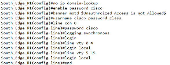
The above configuration has been copied to all switches and
routers which shows that we have configured Banner, enable password, line
console password, line vty password, and remote accesses over telnet.
6.2
Layer-II Port Security.
Port security is configured on the layer II switches to
protect network access from unauthorized devices. We have allowed only the
currently connected devices any other devices than this will not be allowed to
connect with a switch and the administrator will be alerted regarding the
activity.

6.3
VTP Protocol Configuration
VTP is a
VLAN Trunking protocol for making the VLAN configuration process fast by making
one of the switches as a server and the other switches' clients. Any VLAN
configured on the server will also be created on the clients automatically.
VTP
Server

VTP Client

6.4
VLAN Configuration
VLANs have
been configured in the network to divide the network into segments that
introduce many benefits in terms of security, scalability, and resiliency.
Below VLANs have been configured on the switches.

6.5
Layer-III IP Routing
The
layer-III Ip routing has been enabled on the multi-layer switches for enabling
inter-VLAN communication. Below is the configuration done for this purpose.

6.6
DHCP Configuration
We have configured
DHCP on the multi-layer switches to provide redundancy at the first hop. The configuration has been done as below. All IPs that we don’t want the DHCP
server to assign have been excluded.


6.7
Ether Channel Configuration.
Ether
channels have been configured to enhance bandwidth and redundancy.
Configuration has been done as below.

6.8
HSRP Protocol Configuration.
We configure HSRP for providing redundancy at the first hop
by configuring the Host standby routing protocol (HSRP). Configuration for this
has been done at the multi-layer switches. One of the switches is working as the
Active switch and the other switch is acting as the Back-Up switch.

6.9
OSPF Routing Protocol Configuration
OSPF is the most loved enterprise network protocol, we have
configured OSPF on all routers to advertise the connected routes of the routers. The configuration has been done as below.

6.10
Telnet Configuration for Remote Management.
Telnet is used for remote management of network devices. We
have created a local user and allowed it on the VTY lines for remote access.
Devices can be accessed over telnet as below.

6.11
WLAN IoT Device Configuration.
For the IoT devices, we need to configure them by adding the
server IP to each device so that the server would be able to manage devices.
Below WLAN & Server related configuration is done on the IoT devices.


7
Service & Connectivity Test
In this
section, we will verify the connectivity test and verification of the configured
services on the network.
IT_Admin_PC to North Servers Ping
The ping is
successful for all the servers of North Data Center.

Accounts PC- North Datacenter
All servers from this region are also accessible from the
headquarter.

*****************************************************************************
Packet Tracer file will be provided upon request
*****************************************************************************


No comments:
Post a Comment