Unlike other routing protocols, OSPF does not carry data via a transport protocol (UDP, TCP). Instead, OSPF forms IP datagrams directly, packaging them using protocol number 89 for the IP Protocol field. It is an IGP means an interior gateway routing protocol that is used for communication in the same autonomous system. OSPF is the most loved protocol in the industry due to its useful features. From the calculation of the routes in the network, it uses an algorithm called Dijkstra Algorithm which calculates the shortest path from source to destination. Initially, all OSPF routers gather the information of their connected networks which is called link state database LSDB, then they share this information with other OSPF routers, and then the information is populated in the whole network. After gathering information the routers start calculating their shortest path to the destination, this calculation is based on the total cost through an interface.
Based on the
configuration type, OSPF can be used in a single-area network or a multi-area
network.
·
Single Area OSPF
Here we have only one area for all routers and that is Area 0 which is also called the backbone area. We use single area OSPF for comparatively small networks.
·
Multi Area OSPF
Large
networks are divided into different areas to reduce the number of link state advertisements
and other OSPF overhead traffic. This traffic is confined to the same area and
not shared with other areas.
This
division of a network into areas give us a concept of different type of routers
based on their location in the network. Below are the different router types of
an OSPF network.
Router types
·
Internal router (IR): Router located in a specific area.
·
Area border router (ABR): This router has one leg in Area 0 and another leg in any other Area.
·
Backbone router (BR): Router Area 0 is called backbone router,
·
Autonomous system boundary router (ASBR): The boundary router after which a different autonomous
system with a different routing protocol starts
Router id
The unique ID for the Router in the OSPF
topology is known as the Router ID. The router ID is a 32-bit IP address
assigned to each OSPF router.OSPF router ID should not be changed once the neighborship
establishes because changing the router ID resets the OSPF Process and neighboring
routes get reset.
·
Router ID can be configured
manually.
·
If no router-id is configured, the
router makes the highest loopback IP as the router ID.
·
If no loopback IP is configured, a
router selects the highest active interface as the router ID.
We can configure router ID using the below
commands
R1>enable
R1#configure
terminal
R1(config)#router
ospf 100
R1(config-router)#router-id
10.10.10.10
R1(config-router)#exit
R1(config)#exit
Router Attributes
·
Designated
router (DR): A router that is the main centralized router that controls an
area.
·
Backup
designated router (BDR): It acts as an assistant of the DR routers and acts as
DR in case of failure of the DR router.
OSPF neighborship
establishes after exchanging certain messages that are called Link state advertisements.
Below is the message type that OSPF routers exchange with each other.
OSPF messages
·
Hello -> used by a router to
discover neighbor routers and establish neighbor adjacency
·
Database Description (DBD)
·
Link State Request (LSR)
·
Link State Update (LSU)
·
Link State Acknowledgment (LSAck)
Single Area OSPF Configuration
In single area OSPF, we have the same Area for
all networks and the area is normally Area 0. Here we are again using the same
topology now configured with the OSPF routing protocol.
Below are the configuration steps for the OSPF
routing protocol.

R1
The connected routes of R1 are advertised in
OSPF process 1 and Area 0.
R1#conf
t
R1(config)#router
ospf 1
R1(config-router)# network
10.10.10.8 0.0.0.3 area 0
R1(config-router)#
network 192.168.10.0 0.0.0.255 area 0
R1(config-router)#exit
R2:
For
successful neighborship between the two routers the Process ID, Area number,
and the point-to-point network should be correctly configured.
R2#conf
t
R2(config)#router
ospf 1
R2(config-router)# network
10.10.10.8 0.0.0.3 area 0
R2(config-router)#
network 192.168.20.0 0.0.0.255 area 0
R2(config-router)#!
After the configuration of the above steps on
both of the routers, a successful neighborship is established between the
routers, and this neighborship can be checked with the below command.

As the neighborship has been established, now
the routers can successfully share their network information with each other in
the form of the routing table.
Router R1 is learning the network connected to
R2 through OSPF protocol and R2 should learn the networks connected to R2.
The information of router ID, subnets, Area,
and all OSPF advertised networks can be seen with the below command.

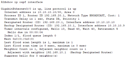
The status cost and states of OSPF at the interface
level can be queried with the below command.
Multi-Area OSPF Configuration
In multi-area OSPF as the name indicates, we
have multiple areas at least two. The main requirement of Multi Area OSPF is
that all other areas should be connected to Area 0 to exchange routing
information.
Let’s take the below topology where we have
two different areas (Area 0 and Area1 ) communicating with each other. The
routers that are having one leg in the other area are called ABR or Area border
routers. In our topology, ABR_0 and Rarea1_1 are the area border routers.

Let’s see the configuration of the Area border
routers which enable the communication between the routers.
RArea1_1
RArea1_1#conf t
RArea1_1(config)#router
ospf 1
RArea1_1(config-router)# network 11.11.11.4
0.0.0.3 area 0
RArea1_1(config-router)# network 11.11.11.8
0.0.0.3 area 1
RArea1_1(config-router)#!
On the router RArea1_1, we have configured the
above networks according to the location of their networks. One leg is
connected to Area0 and the other is located in Area1.
ABR_0
The below configuration has been done of the
Area 0 ABR routers to establish neighborship relation with the other ABR of
Area 1
ABR_0#conf t
ABR_0(config)#
ABR_0(config)#router
ospf 1
ABR_0(config-router)#
network 10.10.10.8 0.0.0.3 area 0
ABR_0(config-router)#
network 192.168.20.0 0.0.0.255 area 0
ABR_0(config-router)# network 11.11.11.4 0.0.0.3 area 0
Each ABR has established two neighborship relations, one with its local router and the other with the other Area, Area Border router.

Routing Table of Multi-Area OSPF
ABR_0
The routes with “O IA” are the inter-area
routes, this router is getting these routes from a different area and that is
Area 1.

RArea1_2
The router RArea1_2 is learning below “O
IA” routes from Area 0 via its area border router

Packet Tracer file with configuration logs and script is available and may be provided upon request


No comments:
Post a Comment